Higher gas velocity
Less prone to entrainment and flooding than wire mesh demisters — vane separators handle gas loads at velocities 30–40% higher, which closes the efficiency gap.
Engineered gas/liquid separation systems — designed, built and installed for the world's most demanding industrial processes.
Lechler is a leading specialist in liquid–gas separation and liquid–gas integration. Our competences are applied across a wide range of industries — both for new installations and for optimising existing processes — with a particular focus on separating droplets from a gas stream. To deliver the best possible support, we keep every discipline in-house.
Lechler develops, supplies and installs complete high-end droplet separators and separator systems for every industrial application. Our highly skilled team of engineers and installation technicians takes on each project individually. Systems are pre-visualised in 3D using Autodesk Inventor, with the design integrated directly into the customer's production environment. This dramatically shortens lead times, lowers cost and lets you see the end result already at the quotation stage.
In many production processes liquids and gases come into contact, and at the end of a process phase the two must be separated. Incomplete separation makes the process unprofitable and, when the gas stream is emitted to atmosphere, places an unnecessary burden on the environment. Apart from special cases, the liquid is removed by mechanical separators that exploit mass inertia — typically radial separators, cyclones, vane type separators and wire mesh demisters.
The key performance criteria of a droplet separator are separation rate, limit droplet size and pressure loss. The limit droplet size is the smallest droplet diameter that can be separated completely; smaller droplets are only partially captured — the so-called fractional separation rate.
Further reading: Background article on droplet separators.
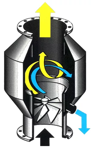
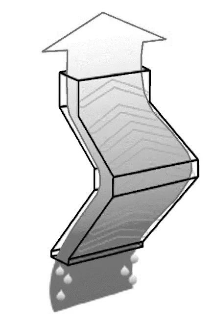
The radial separator is a swirl-type separator — a special design of axial cyclone without current reversal. It is often used under harsh operating conditions where large quantities of liquid must be separated as coarse droplets and where the gas flow may also contain solids. The separation efficiency is typically 98–99% for a limit droplet size of around 50–100 µm, with pressure losses of 6–15 mbar.
The incoming exhaust gas is accelerated by a fixed swirl generator. Curved blades prevent inlet losses and flow deviation; a stable, trouble-free rotational current forms in the spiral tube behind it. Centrifugal force throws droplets outward to the wall, where they are collected.
Because of the special profiling, the separated liquid runs downwards rather than being dragged with the gas, and is collected at the vortex body. The same design promotes self-cleaning of the spiral pipe's inner wall.
In critical applications, deposits on the separator and swirl-body blades can be avoided with additional rinsing systems. These can be operated during normal service without re-introducing droplets into the cleaned gas. Radial separators are specifically dimensioned for higher liquid loads.
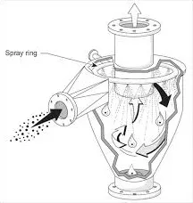
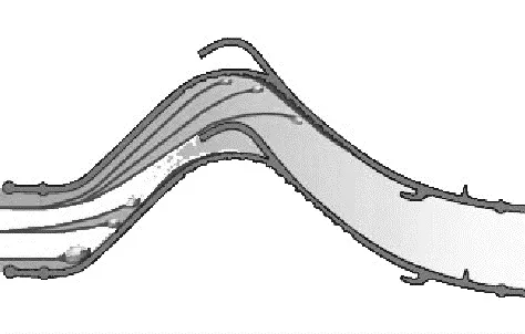
Centrifugal force throws droplets to the outer wall, where they coalesce into a liquid film that runs down to be collected. Cyclones are used in cases similar to radial separators, but they reach smaller limit droplet sizes at the cost of higher pressure losses. Typical performance: 98–99% separation efficiency at a limit droplet size of 30–50 µm, with 10–20 mbar pressure loss.
The limit droplet size decreases as pressure loss across the cyclone rises. For a given application, a large cyclone has lower droplet-separation efficiency than a small one.
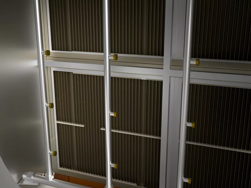
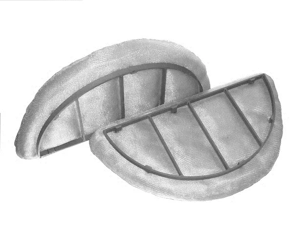
Vane type separators consist of parallel profiles whose shape and length determine separation efficiency. With greater curvature and a more complex profile, finer droplets can be removed thanks to mass inertia. Vane separators are used wherever a finer droplet spectrum must be removed from gas streams, both vertical and horizontal.
The risk of dirt deposition — greater than for radial separators or cyclones — is manageable through continuous or intermittent flushing. In extreme cases a multi-stage system is used, with the first stage flushed especially intensively. Vane type separators reach high separation rates of up to 99.9%.
Vertical and horizontal flow geometries differ mainly in pressure loss, limit droplet size and admissible gas velocity. Vertical separators reach a limit droplet size of about 40 µm; horizontal separators reach 10–20 µm.
In a vertical-flow vane separator the vanes are tilted close to the horizontal so the liquid runs down against the gas. The profile is designed with low-velocity zones in which deposited droplets accumulate (agglomeration) without re-entering the gas flow above them; these zones also help drain the liquid out of the lamella separator.
Horizontally flown vane separators have different design features for secondary separation: the vanes stand perpendicular to the gas direction, and gravity drains the liquid downward. Low-flow zones in front of, inside and behind the phase separation chambers ensure the liquid drains without re-contacting the gas. Because gravity does the work, performance is high — flow rates up to 10 m/s are allowed.
Further reading: Knock-out drums.
A droplet-laden gas stream is passed through a frame of curved, profiled vanes. As the flow deflects between the vanes, mass inertia carries entrained droplets out of the gas stream. The geometry of the deflection, the gas and liquid parameters, droplet size and droplet load determine whether a droplet follows the gas through the deflection or strikes the profile wall of the vane.
Droplets that contact the separator profile under the design conditions form a liquid film and are counted as boundary droplets. Droplets larger than or equal to this boundary diameter are 100% separated; smaller droplets are separated only partially — the fractional separation rate, which is used to assess overall performance.
The lamella shape and the design of the vanes ensure that the liquid film built up by primary separation is fully drained out of the gas stream. Specially shaped discharge profiles are added to the vanes for this purpose. Separation systems engineered for low pressure losses use guide grooves rather than applied discharge profiles.
The shape and size of the discharge profile depends on the application. Together with the number of deflections, it has a major influence on the system's overall pressure loss.
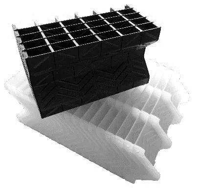
Like a vane type separator, a wire mesh demister works on the principle of mass inertia. When droplets to be separated are significantly smaller than 10 µm, a wire mesh demister is the right choice. The demister is built up from thin wire knitted into a three-dimensional mat, which can be made in almost any shape and used in vertical-flow applications. Smaller diameters are produced as one piece; larger surfaces are split into segments so the demister can be removed through a manhole.
The mat composition determines efficiency: thinner wire packed more densely separates the smallest droplets. Rinsing a wire mesh demister is difficult, so its use is limited to liquids that do not foul the mesh.
Typical performance is 99.9% separation for limit droplet sizes of 5–20 µm. Pressure losses are 1.5–4 mbar — appreciably higher than vertical vane separators — and depend strongly on the liquid load. Because they clog easily, wire mesh demisters serve only as a fine-separation stage.
Droplets pass through the mat, collide with the wire surface due to inertia, agglomerate at the wire intersections and fall back as larger droplets. Performance increases with gas velocity; above the optimum, flooding sets in and droplets are re-entrained. Through special construction, deposit sizes down to 3 µm can be achieved with 99.9% fractional separation.
Wire diameters typically vary between 0.1 mm and 0.5 mm; specific surface areas range from about 100 m²/m³ to 1,100 m²/m³. Specially designed support and cover grids provide roughly 90% free flow area. The mat must fit snugly to the column wall to prevent bypass. Standard mat heights are 100–150 mm; condensation-driven fine droplets may require taller or multi-layer constructions.
The same fundamentals lead directly to a sizing procedure. In a given application, a droplet separator has an optimal operating range. Above it, performance is hampered by entrainment and flooding; below it, efficiency for small droplets drops faster than for large ones until the smallest droplets fall to an unacceptable level — the lower velocity limit.
A widely used formula generalises performance from air/water to other gas/liquid systems. The Souders–Brown equation has long been the standard for the maximum allowable vapour velocity in a packed column:
K = VG √((ρL − ρG) / ρG)
The K-factor expresses an effective gas velocity adjusted for liquid and gas density — a single parameter that lets the separator be sized from collected air/water data. Design K-factors for both horizontal and vertical separators apply only at low to moderate liquid loadings (up to ~0.1 vol-%, equivalent to about 0.5 l/min·m² at 3 m/s); above that, K must be corrected. Lamella separators are less sensitive to liquid-load effects on capacity.
Source: M. Souders and G. G. Brown, Design of Fractionating Columns. I. Entrainment and Capacity, Industrial & Engineering Chemistry 26 (1934), pp. 98–103.
Wire mesh demisters separate finer droplets, but vane type separators win on robustness, throughput and tolerance to dirty service. The nine points below summarise where vane separators have the edge.
Less prone to entrainment and flooding than wire mesh demisters — vane separators handle gas loads at velocities 30–40% higher, which closes the efficiency gap.
Vane type separators typically process loads 5–10× higher than wire mesh demisters — up to 500 l/m²·min versus ~50 l/m² for mesh.
Solids that would bind a wire mesh demister pass through the larger openings of a vane separator. Cleaning intervals are far longer and cleaning itself is much easier.
Vane thickness gives a much longer life than wire mesh demisters at the same corrosion rate. Under aggressive conditions, sheet-metal vanes outlast a mesh of the same alloy by a wide margin.
The relatively open construction of a vane separator gives it the edge wherever a few inches of water column matters.
Where high viscosity blocks liquid drainage, a wire mesh demister floods at very low velocities. Vane separators handle far higher viscosities.
Properly secured in a frame, a vane type separator resists violent gas spikes and slurry-like liquids that would deform or destroy even the strongest mesh.
Liquid agitation in mesh demisters makes them poor in foaming service. Vane separators not only drain without foaming — they can actively suppress it.
For the very smallest fractions, the wire mesh demister still wins — it separates droplets a vane separator cannot.
Tell us about your process. Our engineers will come back with a proposal — visualised in 3D before a single bolt is fitted.
Address
Lechler Process Technology BV
't Woud 59
3232 LN Brielle
Netherlands
Phone
+31 (0)181 419 419